How print orientation changes the strength of a personalised 3D figurine
A raised hand, a thin ankle and a guitar neck can belong to the same figurine yet need different treatment before printing. Turning the complete model on the printer changes how those features intersect the layers. It also changes which surfaces face supports, where fine contours become steps and how difficult the finished piece is to release. There is therefore no single orientation that automatically makes every part stronger and every surface cleaner.
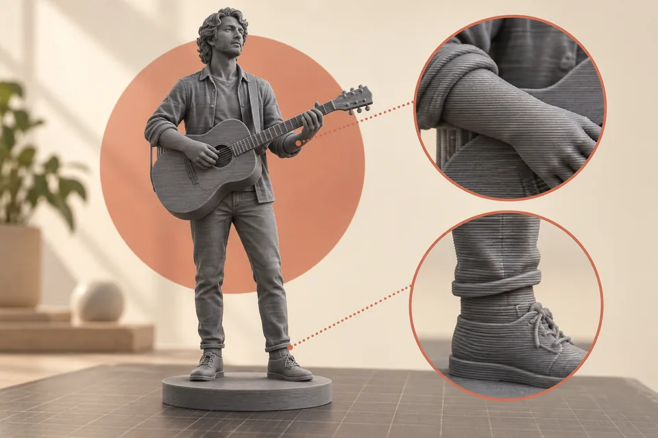
AI-generated illustration: the wrist and ankle highlight connections worth examining. Layers are enlarged for explanation; this is not a photograph of a manufactured print or a test result.
In this guide
For a personalised display figurine, a useful decision begins with the details that must survive ordinary handling: the wrist holding an object, the connection between shoes and base, or a narrow strand of clothing. Their shape matters alongside the direction of the layers. A broad torso may appear robust even when the layer arrangement is less suitable for a nearby projecting accessory. Material in the torso does not describe the local structure inside that accessory.
This guide explains how to examine that trade-off. The worked musician example is an original, hypothetical design exercise, not a report of Formacara production tests. The research cited concerns manufacturing mechanisms, software behaviour and laboratory specimens. It does not establish a certified load capacity for a finished figurine. If you are choosing a design first, the personalised figurine page explains the available starting point; here the focus is the physical arrangement of the print.
Start with three directions, not one label
In ordinary planar FDM printing, the printer deposits paths within a layer and then moves to the next layer. The build direction is perpendicular to those layer planes. The model's orientation describes how the figure sits relative to that build direction. Raster direction describes selected extrusion paths within a layer. These are different choices: rotating infill is not the same as laying a standing figure on its side.
Picture a small baton held vertically. In an upright print, its length may be assembled from many short cross-sections. Turn the baton onto its side and paths can run farther along its length within individual layers. Neither picture describes the complete mechanical behaviour, because perimeters, infill and local geometry still intervene. It does identify why two visually identical objects can contain different internal arrangements.
Use physical descriptions when comparing options: “layers cross the wrist”, “the long axis lies near the layer plane”, or “the face points away from support contacts”. A bare instruction such as “print at ninety degrees” is ambiguous unless the axis and reference plane are stated. Studies and software interfaces do not always use the same angular convention.
For a commissioning discussion, request a screenshot with the print bed visible. Ask for a second view showing the layer preview through the sensitive feature. Those two pictures communicate far more than an isolated angle. They also prevent confusion between the figure's final display position and its temporary manufacturing position.
Why the boundary between layers matters
Deposited plastic must form a bond with material already present. NIST researchers examined how interlayer welding develops under changing thermal conditions and linked molecular processes, measured temperatures and fracture testing. This supports treating the bond as a manufacturing result rather than assuming that adjacent layers behave as one homogeneous block. NIST: weld formation during material extrusion.
A separate NIST study measured individual weld behaviour in ABS. Its value here is methodological: a weld can be investigated separately from the overall part. Its ABS results should not be quoted as the strength of PLA fingers, ankles or hair. NIST: mechanical strength of welding zones.
For a figurine, this means that a thin joint deserves attention even when the surrounding print appears excellent. A clean-looking arm does not reveal every aspect of its internal bonds. Equally, visible horizontal lines are not by themselves evidence of poor adhesion. They may simply describe the ordinary layered surface.
The useful question is how an expected force reaches the joint. If someone catches a sleeve while unpacking the figure, the force can bend the arm at the shoulder. If someone lifts the entire figure by the head, the neck receives a different demand. Neither event can be judged from filament branding alone. The local cross-section, loading direction and actual printing process must be considered together.
Strength, stiffness and resistance to knocks are different
A detail can feel rigid and still break abruptly. Another can deflect slightly without breaking. Stiffness describes resistance to deformation; strength is defined for a particular loading condition and criterion, such as yielding or the maximum tensile stress reached in a test; impact or fracture behaviour concerns different aspects of damage and energy. Calling a figurine “strong” without explaining the expected use bundles these meanings together.
In a PLA study with nine experimental conditions and three specimens per condition, mean ultimate tensile strengths ranged from 16.41 to 53.25 MPa. Several parameters varied across the runs. This is not a universal multiplier for orientation, and a tensile specimen does not predict a figurine’s response to a fall. Experimental PLA parameter study.
For the owner of a display piece, a more useful requirement is concrete: the base should be a sensible place to hold; thin accessories should remain protected while packaging is removed; no narrow joint should be used as a carrying handle. These requirements can guide design even when no numerical strength claim is available.
Also distinguish the force that damages a feature from the event that causes that force. A short drop onto a rigid edge can strike one exposed point. A gentle push can act through a long accessory. The height of a fall, the total weight of the figurine and the length of a projecting object each tell only part of the story. A single laboratory tensile value cannot reconcile all of them.
Map the likely loads before rotating the model
Make a short inventory of what protrudes. Include elbows, wrists, fingers, ears, hair tips, straps, instrument necks, walking sticks and the rim of a hat. Then identify where each protrusion reconnects to a larger volume. A feature may look substantial at its outer end yet narrow sharply at the attachment.
For each connection, imagine three ordinary events: someone brushes against it, packaging catches around it, and the figure is moved to a different shelf. These are design scenarios, not a request to perform destructive tests. Mark the direction in which the connection would tend to bend. The same accessory may need protection in more than one direction.
Now identify the normal grip. If the figure sits on a base, can fingers reach that base without passing between the legs or around a delicate object? If the base is visually hidden, would a recipient instinctively grasp the torso instead? A suitable orientation cannot compensate for a design that encourages handling at its weakest point.
A practical review sheet can contain four columns: feature, likely contact, connection to inspect, proposed response. For a raised trophy the response might be moving the hand closer to the body; for a loose scarf it might be thickening a hidden root; for a guitar neck it might be changing orientation or considering a separate part. The sheet keeps the discussion attached to real geometry.
Upright printing: convenient geometry with local compromises
An upright figure often has an obvious first contact with the bed: its base or the soles of its shoes. The front of the face can remain accessible to printing without resting directly on supports. This makes upright orientation a natural candidate, but a candidate is not a conclusion.
Look at a vertical ankle. Its small cross-section repeats through successive layers while the mass above it grows. Look next at a raised vertical forearm: the wrist can become a similarly narrow stack. The torso may be broad enough that the same layer arrangement attracts little attention. It is the local shape, rather than the word “upright”, that makes the difference.
Meanwhile, a horizontal forearm in an upright figure presents another problem: its underside may need support. Protecting that underside could introduce difficult contact near the fingers or elbow. A pose with one hand against the waist may be easier to manage because the arm reconnects to the body, although the contact must genuinely exist in the printable model.
Review upright printing by moving upward through the preview. Pause where legs become hips, where an accessory first appears, and where a narrow neck carries a head. Do not infer those connections from an attractive shaded rendering. The layer sequence shows whether there is actual deposited material joining the regions and whether the support plan introduces a new handling problem.
Sideways or tilted: what improves, and what moves elsewhere
Laying a figure down changes which long features run near a layer plane. A slender limb that crossed many layer boundaries may gain longer continuous paths along its length. At the same time, an ear, cheek, shoulder or jacket surface may become an underside. The improvement at one joint can therefore be accompanied by more visible support contacts elsewhere.
A slight tilt deserves the same scrutiny as a large rotation. It is not a universal compromise. Depending on the pose, it may move support contacts away from the face, or it may place them on a previously clean cheek. It may improve the orientation of one arm while leaving the other in a less favourable arrangement.
Compare whole configurations, not just angles. Save an upright version and one or two alternatives. For each, record the critical joint, the principal viewing surface, support access and the grip needed during removal. An option that scores well on the first three but requires twisting a thin wrist to remove support remains a poor practical choice.
When discussing a tilted print with a customer, separate the manufacturing view from the finished view. The figurine does not need to be displayed at the same angle at which it was built. A rotated screenshot can otherwise make the posture seem altered when only the printing setup has changed. Keep a stable front reference beside the technical view.
Surface appearance has its own directional problem
A curved face, a rounded shoulder and a sloping hat brim intersect flat layers differently. Where a surface changes gradually with height, layer contours can appear as terraces. Orientation changes their spacing and placement. Research on FDM PLA surface roughness explicitly investigated printing angle; its measurements also depended on the direction of measurement. Study of orientation and surface roughness.
That finding should encourage careful viewing rather than a single aesthetic ranking. A surface that looks smooth from the front under diffuse light may show contours under light from the side. A ridge on the back of a jacket may be visually minor, while a similar ridge across an eyelid changes the expression.
Choose a principal viewing zone before choosing a printing orientation. For a desk figurine this might be the front and a three-quarter view. For a piece intended for the centre of a table, the rear deserves more weight. There is no need to pretend every square millimetre has equal visual importance.
An original way to document the choice is to mark the model in three categories: expression and identity, recognisable clothing or objects, and low-visibility underside. This is an editorial design aid, not a manufacturing standard. It helps explain why a small support mark beneath a coat may be acceptable while the same contact on the nose is not.
Finer layers do not resolve every small feature
Layer height controls sampling in the build direction. It does not independently define every narrow line in the horizontal plane. Prusa's documentation distinguishes vertical resolution from features constrained by extrusion width and nozzle choice. Prusa: layers and perimeters.
For a personalised figure, consider a raised eyebrow, an engraved jacket line and a thin spectacle arm. These details occupy different planes. Reducing layer height may alter one more than another. If a narrow feature disappears from the generated paths, a finer vertical step alone may leave it absent.
Variable layer height can concentrate finer layers in selected height regions, as documented by Prusa. This provides an additional option for curved regions, but it does not rotate the layers or prove the strength of a joint. Prusa: variable layer height.
Ask two separate questions in review: is the feature represented, and is the represented feature suitable for handling? A one-path whisker may be present in the preview yet remain an unsuitable exposed element for the intended display piece. Conversely, a slightly simplified eyebrow can preserve the expression without reproducing every contour. Resolution should serve the intended sculpture, not become an isolated number used to rank it.
A seam is not the same as a crack
Each closed perimeter needs a start and end. Their placement can create a visible seam, and slicers provide controls for positioning it. That is a normal process feature which should be distinguished from an open separation between layers. Prusa: seam position.
On a round head, a line of small surface irregularities can attract attention because there is no garment fold to hide it. On a jacket, the same line may be easier to place beside a natural edge. Rotating the figure may change both the seam options and the support pattern, so the two should be reviewed together.
For inspection, describe what you actually see. “A narrow raised line behind the left shoulder” is more informative than “the layers are broken”. An open gap, a displaced section or a line that continues across a joint deserves a different assessment. Photographs from two angles can help a maker distinguish the possibilities without asking the recipient to bend the part.
Do not sand an uncertain defect immediately. Abrasion can remove the evidence needed to understand it and can reduce an already thin feature. First establish whether the issue is a cosmetic seam, residual support, a model edge or damage. The action depends on that distinction, not on the fact that all four can look like a line in a close-up photograph.
Supports must be removable, not merely printable
Supports give otherwise unsupported regions a temporary foundation. Official guidance describes orientation changes and splitting a model as ways to reconsider where supports are needed. Prusa: support material.
The important extension for a figurine is to plan the exit route. Imagine the support as a physical object after printing. Can it leave the gap between an arm and torso? Does it wrap around a narrow handle? Can its contact be reached while the surrounding figure is held at a broad, stable region?
A support that prints successfully can still be badly placed for removal. For example, material under a raised hand may be accessible from below, while material enclosed by a circular handle may need to be broken into small sections. The second arrangement adds handling steps around an already delicate detail. This is a reason to review the geometry early, before focusing on the quantity of support.
Prusa's organic support documentation describes a different branching approach from older grid structures. The available support style is therefore another variable, but its name does not guarantee clean contact or easy removal on every model. Prusa: organic supports.
For a customer, the useful outcome is a clear statement of which areas may retain contact marks and which features need extra protection. The internal software setting matters less than that visible, practical consequence.
Thin features need a path check
A digital surface can be closed and visually convincing while containing details that the chosen printing setup cannot represent satisfactorily. Manufacturer guidance identifies thin walls and minimum feature size as constraints that must be considered during modelling. Prusa: modelling for 3D printing.
Modern perimeter generation can vary extrusion width. Prusa's Arachne documentation also specifies a minimum feature threshold: some details are widened and others can be omitted. That makes the actual path preview essential. Prusa: Arachne perimeter generator.
For a figurine, inspect the whole length of a strap or finger rather than one representative slice. A detail can be adequately represented near the palm and diminish to an isolated path at its tip. A different orientation changes the cross-sections presented to the slicer, which can change where this transition occurs.
Avoid turning a software minimum into a promise of durability. “The slicer generates it” means that a path exists. It does not answer whether the detail survives removal, packaging or ordinary handling. A practical design may preserve the outline while connecting the feature to a neighbouring surface. That decision should be shown clearly in the preview because it changes the sculpture, even when it improves its practicality.
Perimeters and infill answer different questions
Increasing the interior fill of a broad torso does not automatically solve a wrist whose cross-section is almost entirely wall paths. Before discussing percentages, inspect how much interior space the critical feature actually contains. If there is no substantial infill region there, changing the global percentage may mostly affect other parts of the figure.
This is why a local question is more useful: what material path crosses the vulnerable connection? The answer can involve outer walls, inner walls, solid regions and the way the feature joins its neighbour. A single setting cannot describe the complete load path.
Do not infer that maximal fill is always desirable, or that a larger wall count is always feasible at the same scale. The settings need room within the geometry. If a thin accessory cannot accommodate the intended structure, enlarging or simplifying that accessory may be more meaningful than changing a number in the print profile.
When reviewing quotations or production explanations, prefer evidence attached to the model: a cross-section through the wrist and another through the torso, for example. The comparison makes it clear why the same global settings create different local structures. It also avoids judging a display figurine as though its only meaningful property were its total mass. More plastic somewhere else is not automatically more protection where a recipient is likely to touch it.
Cooling and print history remain part of the result
Orientation changes the order in which regions appear and how much time the printer spends on each layer. A tiny raised finger near the end of a print is a different situation from a broad layer across the torso. Prusa documents cooling controls because newly deposited material needs appropriate solidification, particularly around overhangs and bridges. Prusa: cooling.
This does not justify prescribing one fan speed, temperature or printing speed for all figurines. The machine, filament formulation, nozzle and geometry form a system. A published experiment is useful within its documented conditions; copying a temperature without those conditions can be misleading.
For a production review, record the profile used and avoid changing several variables while trying to understand one observed defect. If the wrist changes orientation, the support strategy and the cooling profile simultaneously, a better result will not reveal which change mattered. A modest comparison is easier to interpret when its differences are explicit.
For a buyer, the corresponding question is simple: has the maker reviewed this pose at this size, or only a larger or simpler model? That is a request for relevant evidence, not for proprietary machine settings. A responsible answer can acknowledge that a particular thin feature requires redesign or an additional check. Such a limitation is more useful than a blanket assurance that the material is strong.
The base and the first layers deserve separate attention
The connection to the base is both structural and practical. A wide plinth can offer a sensible grip, yet the figure may still connect to it through two small ankles. Conversely, a seated pose may contact the base through a larger region. Compare the actual connections rather than assuming a larger base resolves everything above it.
The first layer also has its own dimensional behaviour. Prusa describes “elephant foot” as a widening near the bed which can matter for fitting parts together. Prusa: elephant foot compensation.
A brim is another distinct element: it is temporary material around the first-layer footprint intended to assist bed adhesion. It should not be confused with a permanent base designed into the figurine. Prusa: skirt and brim.
During design review, show the permanent silhouette without temporary printing aids. A recipient should not discover that the stable-looking outline in a technical screenshot included material that will later be removed. Similarly, if the base is printed separately, show the intended assembled position and ask how the figure is located on it.
For final inspection, use a level, stable surface and observe whether the base sits as intended. Do not press a warped or rocking base flat by pushing on the head. That transfers an unrelated problem into narrow joints farther up the figure.
A faithful outline and a strong connection are separate checks
A PLA experiment on geometric quality examined orientation, layer thickness and feed rate in relation to dimensional accuracy, flatness and surface texture. Its findings concern those measured geometric outcomes, which are distinct from mechanical strength. Research on PLA geometric properties.
For a figurine, this distinction becomes useful when an accessory must meet a hand or a shoe must meet a separate base. The silhouette might look correct while a local fit requires adjustment. Conversely, a connection might fit together while leaving an unwanted visible step. Neither observation alone establishes how the connection responds to handling.
Keep appearance, fit and mechanical suitability as separate entries in the review. A photograph can document the assembled outline. A relevant dimensional check can document the fit. A defined loading test, where appropriate, addresses a different question. Combining these observations is sensible; silently substituting one for another is not.
This also helps when requesting a revision. State whether the concern is a gap, a visible offset, an inaccessible connection or damage. The maker can then investigate the relevant feature without treating every issue as a reason to rotate the entire model.
When separating a part can be worth considering
A single orientation may be an uncomfortable compromise when the figure contains long features in several directions. Splitting can allow different orientations for different parts. Prusa's cut tool explicitly supports separating models and adding connectors for assembly. Prusa: cut tool.
For a hypothetical musician, separating the instrument might protect its neck while leaving the face in a more favourable printing position. But separation introduces a joint. Its fit, visibility, alignment and assembly procedure need their own review. It is not automatically stronger merely because each component prints more conveniently.
A useful joint location may coincide with a sleeve edge, belt or object boundary. That is an aesthetic design judgement, not a guarantee. The proposed line should be shown in the assembled view, especially in a single-colour finish where shadows may reveal a small step.
Also consider the recipient. A fully assembled display piece and a kit requiring attachment are different products. Do not silently transfer a difficult assembly task to the customer to solve a production problem. If separate parts are an option, establish who assembles them and how they are inspected before discussing the arrangement as a finished solution.
This guide does not claim that every Formacara design uses, offers or requires separate components. It describes a manufacturing option that a maker can evaluate when one-piece orientation cannot satisfy the relevant constraints.
Worked example: a musician holding a guitar
Imagine a proposed figurine, about the height of a small desk ornament, with a guitar across the torso. The right elbow projects outward. The left hand reaches along a narrow neck. Both shoes meet a modest base. These details are illustrative; no dimensions or settings here are validated production specifications.
The first task is to define what carries the identity of the scene. Suppose the customer values the forward tilt of the head, the guitar shape and the relaxed elbow. The exact space between the instrument and jacket is less important. Write that distinction down before changing geometry. It creates room for a practical adjustment without accidentally removing the gesture that made the photograph meaningful.
Next identify vulnerable connections: both ankles, the projecting elbow, the wrist along the guitar neck and the end of the neck beyond the hand. Mark a principal viewing direction from the front and slightly to the left. Now review three candidates: upright, tilted backward, and a configuration in which the instrument is considered separately.
Do not score these candidates with invented percentages. The purpose is to reveal questions. Does the upright version place supports beneath the elbow where they can be removed? Does the tilt move contact onto the back of the head? Does a separate instrument create an awkward joint at the hand? Each answer must come from the actual model and preview.
Candidate A: upright, with a revised contact
Suppose the preview shows that the underside of the elbow is accessible, but the guitar neck remains exposed beyond a thin hand. Instead of immediately rotating the complete figure, consider a slight change that brings the instrument closer to the shoulder or torso. The change could create a secondary contact while preserving the front silhouette.
This is a design hypothesis, not a proven reinforcement. Inspect the contact in the printable geometry and in the layer preview. A near-touch visible in a rendering is not enough. It also needs to remain visually acceptable from the agreed three-quarter view.
The decision record might read: “Retain upright candidate; evaluate a discreet instrument-to-body contact; verify the free end beyond the hand; keep support contacts away from the facial features.” This tells the next reviewer what is unresolved and why. It is much more useful than a label such as “strong profile”.
Candidate B: tilted, with a different visible underside
Now imagine that the backward tilt improves the path arrangement along one ankle but places a larger region of the jacket and head near supports. Inspect those areas at normal display distance, not only at extreme zoom. A small mark on the back may be acceptable if the object will face outward from a shelf, but less acceptable for a centrally displayed piece.
Review removal access again. The tilt may create an enclosed support region between the guitar and torso that did not exist in the upright candidate. That extra difficulty can outweigh a theoretical local benefit. The decision should account for the complete manufacturing and handling sequence.
The record might say: “Keep as alternative only if support removal remains accessible and rear contact marks meet the agreed appearance.” No precise strength gain is asserted because none has been measured.
Candidate C: separate instrument, added assembly question
A separate instrument permits an orientation chosen around its own shape. Yet the hand-to-instrument relationship now needs alignment. If the pose depends on fingers wrapping closely around the neck, the assembly could be difficult or require a visible opening.
Ask whether the resulting joint is broad enough to locate the part consistently and whether it remains visible after assembly. Consider how the assembled piece will be supported during handling. A convenient manufacturing split is not enough if it creates a fragile connection exactly where people naturally grip the object.
The decision might be to reject separation and accept a modest sculptural simplification. It might instead be to retain separate parts after a specific fit and appearance check. Either conclusion can be reasonable. The value of the exercise is that it exposes the trade-off rather than hiding it behind an arbitrary angle or infill percentage.
An inspection protocol you can print and use
The following protocol is an original review aid for decorative figurines. It is not a standardised mechanical test, certification procedure or proof of hidden bond quality. Use it to record observable features and to avoid damaging the object while trying to decide whether it is acceptable.
Before printing, record the model version, intended height, permanent base, principal viewing direction and the three most sensitive details. Save the chosen orientation with the bed visible. Save a layer-preview image through each sensitive connection. Record where supports touch the finished surface and how they can be removed. Mark any change to the pose that needs agreement.
Before unpacking the finished piece, identify the base or other broad holding area. Open the packaging so that exposed accessories are not used to pull the figure free. If wrapping is caught around a thin feature, release the wrapping while supporting the larger body; do not pull the feature through a tight opening. Stop if the removal route is unclear.
Under diffuse light, inspect the full silhouette from the front, both sides and rear. Then use light from an angle to locate unexpected gaps, displaced regions or rough support contacts. Observe the ankles, wrists, neck and accessory roots without bending them. Record the location and take photographs if anything is uncertain.
Place the figure on a stable surface and confirm that it sits as intended. Check the agreed appearance at normal viewing distance. A close-up remains useful for diagnosis, but it should not replace the actual display context when evaluating minor surface texture.
Finish with one of three outcomes: accepted as observed, clarification required, or visible damage requiring maker review. Do not use “passed strength test” as an outcome unless an actual, appropriate mechanical test has been defined and performed. This protocol deliberately makes no such claim.
Reading a test report without overextending its conclusion
If a maker supplies test information, begin with the specimen rather than the headline number. Was the tested object a standard tensile bar, a simple printed connection or the exact figurine? Those objects answer different questions. A bar can characterise a material and process under controlled loading; a representative joint can investigate a local design; a complete figurine includes the interaction of several features. None should silently stand in for the others.
Next look for the direction of loading. If the report says only “horizontal” or “vertical”, establish whether that describes the specimen, the build direction or the test machine. Ask whether the filament grade, orientation and relevant print configuration match the proposed object. A result with an unspecified material or missing orientation remains incomplete evidence, even if the numerical value is precise.
Look for repeated specimens and variability. One successful print can show that a particular geometry was produced, but it does not establish consistent production performance. Equally, one broken item does not by itself identify orientation as the cause. Photographs of the failure location, the loading arrangement and the paths through that location are more informative than an isolated pass or fail statement.
The practical consequence is to make claims proportional to the evidence. “The support can be removed from this prototype without contacting the wrist” is a limited, observable claim. “The wrist cannot break” is a much broader assertion and is not supported by the same observation. Keeping that distinction clear protects both the buyer's expectations and the maker's ability to explain a considered design.
A compact record for revisions and repeat orders
Personalised figures can be revised several times before printing. Save the reason for each relevant change alongside the new model version. If a hand moved closer to a coat to improve support access, say so. If a face was rotated away from support contacts, retain the previous and new views. This avoids later restoring an attractive detail without remembering why it was changed.
Record the selected size separately from the nominal model file. A repeat order at another height should reopen the thin-feature review. It should also reopen the handling question: the larger version may offer a broader grip, while the smaller version may make a previously separate detail visually or physically ambiguous. Neither outcome should be assumed from the scale factor alone.
For a repair or replacement discussion, preserve photographs before modifying the object. Include an overall view, a close view of the affected connection and a view showing the apparent layer direction. Describe when the issue became visible without assigning a cause prematurely. “The accessory was detached when the packaging was opened” is an observation; “the printer used the wrong angle” is a diagnosis requiring additional evidence.
A useful revision record ends with the next observable check. That might be confirming a continuous connection in the layer preview, inspecting a support contact on a sample, or verifying the assembled alignment of a separately printed object. Specific checks make progress reviewable. They also keep the conversation grounded in the actual figurine instead of an abstract debate over which orientation is universally best.
Questions that lead to a better design decision
Ask which feature governed the selected orientation. A useful answer identifies a wrist, an ankle, the face or another specific region. “This is the strongest angle” provides too little context to evaluate.
Ask which surfaces will contact supports and whether those contacts are visible from the main display view. Ask whether the same pose has been reviewed at the chosen size. Scaling down can change the representation of a small detail, so approval of a larger preview should not silently approve every smaller version.
Ask whether any contact, thickening or simplification was introduced to preserve a vulnerable feature. These adjustments can be sensible, but they belong in the design discussion because they affect the sculpture. The figurine size guide can help frame the space available for those details.
Finally, ask where the finished piece should be held. A design that answers this clearly is easier to live with. The care guide covers handling after delivery, while the orientation review addresses the earlier decision about how the object is built.
The best outcome is an explicit balance: a recognisable pose, appropriate treatment of its narrow connections, acceptable visible surfaces and a practical route through support removal and everyday handling. For a custom figurine from a photo, those decisions should serve the person and gesture being represented. They should also remain honest about what has been inspected, what has been tested and what remains a design judgement.